PCB materials and specifications
The laminate sets how a board handles heat, how fast signals travel and how much they lose. This page groups the materials we keep qualified into families and gives the properties you need to choose between them and to model impedance.
- Tg range across our FR-4 grades
- 130 to 180 °C
- Dielectric constant across all families
- 2.2 to 4.7
- Lowest dissipation factor (PTFE, 10 GHz)
- 0.0009
- Layers in the largest standard build
- 24
The properties that matter
| Property | What it tells you |
|---|---|
| Tg, glass transition temperature | The point where the resin turns from rigid to rubbery. Above it the board expands quickly through its thickness, which strains plated holes. Choose a higher Tg for lead-free assembly with several reflows, thick boards and high operating temperatures. |
| Td, decomposition temperature | The temperature at which the resin has lost 5% of its weight. A higher Td gives more margin through repeated soldering. |
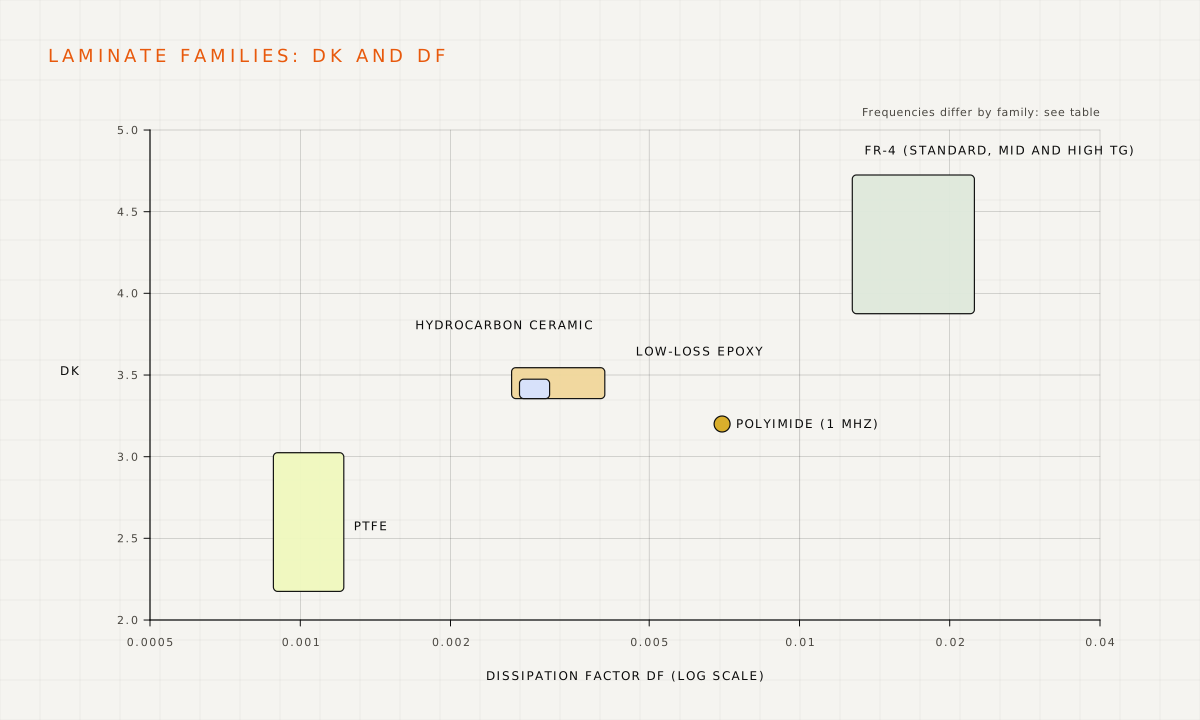
| Dk, dielectric constant | Sets signal speed and, with the geometry, the impedance of a trace. Dk changes with frequency, so always compare values measured at the same frequency. |
| Df, dissipation factor | How much signal energy the material absorbs. Low Df matters for long, fast or RF traces. |
| CTI, comparative tracking index | Resistance to surface tracking under high voltage, given as a performance class (PLC). PLC 3 covers 175 to 249 V and PLC 2 covers 250 to 399 V. A better class allows smaller creepage distances. |
Laminate families
We hold several qualified grades in each family. Your quote names the grade proposed for your build, and we can match a specific laminate or an equivalent if your design calls for one.
| Family | Typical use | Tg (°C) | Td (°C) | Dk (at frequency) | Df (at frequency) | CTI |
|---|---|---|---|---|---|---|
| Epoxy glass (FR-4) | ||||||
| Standard FR-4 | General-purpose boards, single and double-sided, simple multilayers | 130 to 140 | 310 to 315 | 4.2 to 4.6 at 1 GHz; 4.6 to 4.7 at 1 MHz | 0.015 to 0.016 at 1 GHz; 0.016 to 0.02 at 1 MHz | PLC 3 where rated |
| Mid-Tg FR-4 | Multilayers with lead-free assembly | 150 to 155 | 330 to 358 | 4.4 to 4.7 at 1 GHz; 3.9 at 500 MHz | 0.016 at 1 GHz; 0.022 at 500 MHz | PLC 3 where rated |
| High-Tg FR-4 | Thick multilayers, several reflows, high operating temperature | 170 to 180 | 340 to 360 | 3.97 to 4.04 at 2 GHz; 4.2 at 1 GHz; 4.6 to 4.7 at 1 MHz | 0.013 to 0.021 | PLC 3 where rated |
| Black FR-4 | Cosmetic and optical applications | By grade | By grade | Up to 5.4 | By grade | By grade |
| Low-loss and RF | ||||||
| Low-loss modified epoxy | High-speed digital and RF that must laminate like FR-4 | 215 | 360 | 3.38 to 3.45 at 10 GHz | 0.0028 to 0.0031 at 10 GHz | PLC 2 |
| Hydrocarbon ceramic | RF and microwave, antennas, radar front ends; also as bonding plies in hybrid builds | 280 and above | 390 to 425 | 3.38 to 3.52 at 10 GHz | 0.0027 to 0.004 at 10 GHz | Not rated |
| PTFE (glass or ceramic filled) | Lowest-loss microwave and millimetre-wave circuits | Not applicable | 500 | 2.2 to 3.0 at 10 GHz | 0.0009 to 0.0012 at 10 GHz | Not rated |
| Flexible and thermal | ||||||
| Polyimide | Flexible circuits and the flex layers of rigid-flex boards | Not applicable | Not quoted | 3.2 at 1 MHz | 0.007 at 1 MHz | Not rated |
| Aluminium-clad (metal core) | LED and power boards that must spread heat | 120 (dielectric) | Not quoted | 5 to 7 | Not quoted | Not rated |
Values are typical figures from the laminate data sheets for the grades we stock, measured at the frequency shown. Use the data sheet of the exact grade for impedance modelling; we confirm it with your quote.
Choosing a material
- Start with standard FR-4 for most digital and mixed-signal boards up to a few hundred MHz.
- Move to mid or high-Tg FR-4 for boards of eight layers or more, boards thicker than about 1.6 mm, or assemblies that see several lead-free reflows.
- Use low-loss epoxy when long high-speed links (multi-gigabit SerDes, fast memory) run out of loss budget on FR-4.
- Use hydrocarbon-ceramic or PTFE laminates for RF and microwave circuits, often only on the outer layers of a hybrid stackup with FR-4 inside to control cost.
- Use metal-core boards when a power or LED design must move heat into a heatsink through the board.
- Use polyimide for flexible circuits; see the flexible PCB capabilities.
From materials to a stackup
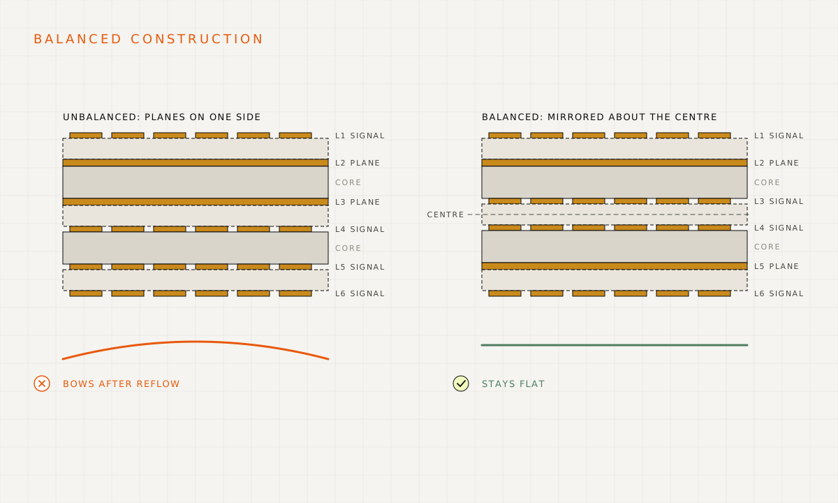
A rigid multilayer is built from cores (laminate with copper bonded to both sides) and prepreg (glass cloth with partly cured resin) that bonds the cores together in lamination. Balanced, symmetrical builds stay flat. Tell us your target impedances and we will propose a stackup with the dielectric heights and trace widths to suit the laminate on your quote.
| Item | Standard capability |
|---|---|
| Layer count | Up to 24 layers |
| Finished board thickness | 0.20 mm (without HASL or solder mask) to 3.20 mm |
| Thinnest core | 0.10 mm |
| Thinnest dielectric between layers | 0.10 mm |
| Inner copper | 0.5 oz to 2 oz |
| Outer copper | 0.5 oz to 3 oz |
| Controlled impedance | Designed and measured on test coupons |
Finishes, mask and legend
| Finish | Thickness | Lead-free (RoHS) | Good for |
|---|---|---|---|
| HASL, tin-lead | 1 to 25 µm solder | No | Low-cost through-hole and coarse-pitch SMT where lead is permitted |
| HASL, lead-free | Solder coat | Yes | General SMT where flatness is not critical |
| ENIG (electroless nickel, immersion gold) | Nickel 3 to 6 µm, gold 0.04 µm minimum (typically 0.075 to 0.10 µm) | Yes | Flat pads for fine-pitch parts and BGAs, wire-free contacts, long shelf life |
| Immersion tin | Thin tin layer | Yes | Flat, solderable pads and press-fit pins |
| Hard gold (electrolytic) | Nickel 3 to 6 µm, gold 0.5 µm minimum | Yes | Edge-connector tabs and contacts that are plugged repeatedly |
Solder mask colours: green, blue, black, white, red, purple, yellow and orange. Legend colours: white, black and yellow. Green and blue mask resolve the finest dams; see the rigid PCB capabilities.
Ready when your files are
Send your design for a quote
Upload your Gerber, drill and assembly files with the quantities you need. Our engineers check them against these guidelines and come back with a price, a schedule and any questions.